
The Louvre, Abu Dhabi
by Jean Nouvel
status: under-construction
“A large, shallow dome, 180m in diameter, floats above the collection of buildings, with only four support points around its perimeter truss. The dome unites this micro-city, and takes up the Islamic tradition of the perforated screen and the use of self- similarity and fractal organization of patterning to create a special micro-climate below. The space beneath is animated by the shadow play caused by the modulation of light by the complex, lacy mesh of small openings across the dome’s surface, reflected on the buildings and the water of the inlet.”
Study of the initial duplication of the fractal pattern

Study of the initial duplication and 12.5 degrees step rotations of the fractal pattern

Result of the initial duplication and rotation of the fractal pattern

Fractal pattern studies

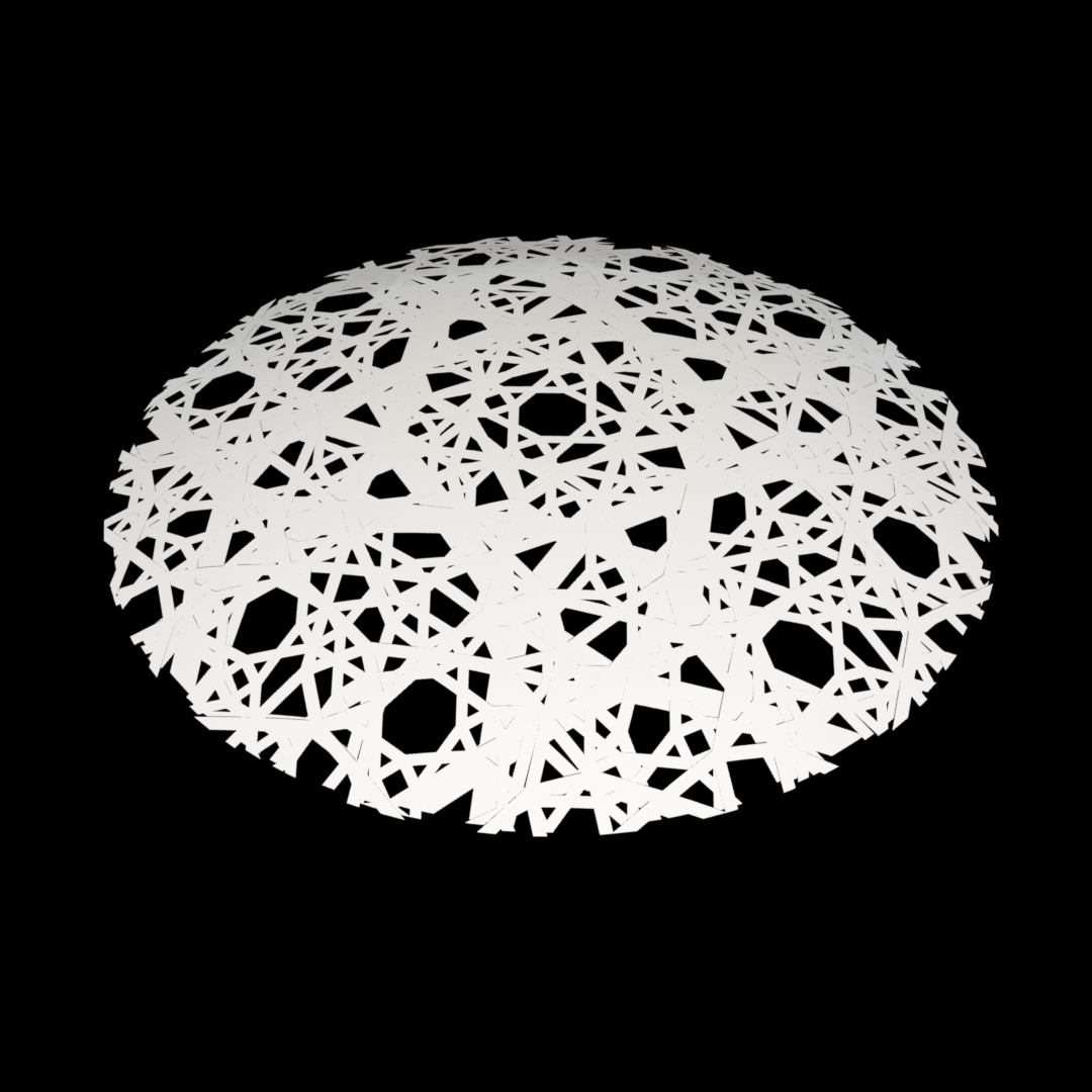
Fractal pattern shadow studies:
This experiment was done using a software called modo. The pattern in this rendering is procedural, not generated from the previous diagrams.

This experiment was done using a software called modo. The pattern in this case is a direct translation of the diagrams into a three-dimensional surface.

Step1: building outlines in Rhino:
The first step was to create the outline of the building in Rhino which is then used in grasshopper to generate the massing. Because of the minimal infor- mation published about the project, not all the masses match the heights in the original design by Jean Nouvel. However, a study of the shadow casting from one of the published renderings provided the proportional relationship between the different heights of the masses. In the image below, each color represents a group of masses that share the same height parameter.

Step2: from Rhino outlines to Grasshopper masses.
The outlines from the previous step were transferred to Grasshopper where every group’s height is controlled by a slider.

Step3: volumes global parameter
The height of the whole building and all its masses is controlled by a multi- plier. This multiplier allows for the change of all the volumes in the design proportionally. This in return will maintain the relationships between all the volumes.

Step4: mass local parameters
While there is a multiplier to control the relationship between the masses, each group of volumes have the ability to change its height parameter lo- cally, which will allow for a greater set of variations.

Step5: dome as flat mesh
In this step the process of creating the dome starts. It will become evident in the following steps why a mesh was used instead of a surface. There are four meshes in total where each layer will be used to create on of the outer layers of the dome.

Step6: from a flat mesh to a dome via Kangaroo
The four meshes created in Rhino in the previous step will be fed to a Kangaroo definition within the over-all definition for the building. By giving Kangaroo a U-Force node in the positive Z direction, the flat mesh takes the shame of a dome.

Step7: extracting meshes
In this step, we take the four different meshes that were fed into Kangaroo and separate them.

Step8: extracting curves from meshes
Here we create a series of curves that define the mesh.

Step9: lofting and subdividing
In #1 we loft the curves created in the previous step to create a surface type object for the dome.
#2 shows the number of subdivisions on the surface which can be increased or decreased parametrically.

Step10: SBox and Box morphing
#1 shows the SBox node which changes each patch on the subdivided sur- face into a box. The depth of the box is also parametric and can be changed.
#2 shows the basic pattern which is inclosed by a bounding box.
#3 is the application of the Morph node, where the pattern in #2 is applied and morphed to the surface adjusting itself to fit in every patch.

Step10: rotation parameter
From the study of the fractals on the dome, it is evident that these panels are rotated at each layer to create greater complexity. Thus in #1 the rotate node was added to the definition to provide the ability of parametrically rotating each layer when needed.
#2 shows the juxtaposition of all the outer layers of the dome where the pat- tern is lost.

Step11: all in all
The following image shows the full definition and the outcome.

Step12: the Louvre as a rendering

