Project 2
Project 1 update...
project 1 updated method I:
Because there were some inconsistency in the results for project 1 , I have decided to revise the method. In project one there were inconsistencies with the sizes of the panels. The panels that were in the middle of the dome had no distortions, however, the panels that were closer to the edge were distorted. In order to solve the problem I have revised the way in which the dome surface is generated.
After extracting the mesh from the Kangaroo engine, I extracted only one curve from each mesh, which is the curve that has the longest span. This curve was then duplicated/offset in both directions. The distance that the curve is moved by was extracted from the original mesh by calculating the area of the original mesh and getting its square root. Thus the curves will always offset parametrically to the size of the mesh, eliminating the possibilities of error.

In this step the three generated curves are lofted to create the base surface for the dome.

Here the surface is divided equally in the both UV directions.

Then the center of each panel is extracted

If we are to imagine the dome being part of a great sphere, we connect the center of the sphere to the new points generated in the center of each division created in the last step to find the normal at that point. Of course there are other methods to find the normal, but I have found this method to have better accuracy when it comes to plane rotation.

The new generated planes

Here, the original curve for a single panel is oriented to the newly created planes on the surface.

Offset the pattern in the positive and negative direction to generate the basic curves for the panels.

Create a planar surface from each series of planar curves, and extrude them based on their normal.

Generate a Box with a Z parameter that stops at the bottom of the desired dome result. This Z value can also be extracted from the original mesh.

The panels and the Box are then differenced to create the final resulting panels for the dome.

project 1 updated method II:
The second method is a combined method of what was done in Project 1, and project 1 updated method I. Basically after extracting the mesh from the Kangaroo engine, we go through the same steps to generate the basic surface of the dome.
The dome out of the Kangaroo engine

Exploding the dome to its elements

Creating a curve that spans the length of the dome.

Parametrically offsetting the curves.

Lofting the curves to create the basic shape for the dome.

Subdividing the dome to prep it for the BoxSurface.

Applying the BBox method as in Project 1 to the BoxSurface.

Generating a parametric box which will then be used for a difference/Boolean operation.

Final outcome of a single layer in the dome.

Final outcome for all Four layers of the dome.

Final outcome of the dome and the project masses.

Project 2 methods:
The basic idea for project 2 is to affect the panels that are applied to the dome. The idea is to create panels that are responsive to the sun. In order to do this, the normal vector of each panel needs to be generated and then compared with the angle of the sun. Where the angle between the normal vector and the sun vector is 90 degrees, the panels elements will become thicker to prevent the sun from penetrating the space. In contrast, where the larger/smaller the angle is from 90 degrees, the panels become thinner because there is no need to provide shading as the sun will be automatically blocked. Because each panel will be affected differently, the BBox method used in Project 1 will not work.
Three different methods were used to create the desired affect. All three methods use projection to generate the pattern on the dome surface.
Project 2 method I : By distance from the flat pattern
This is the simplest and most straight forward method. The basic idea is that we can conceptually consider the sun at a very close proximity to the building. By doing so, we can compare the distance between the sun and each panel/curve .
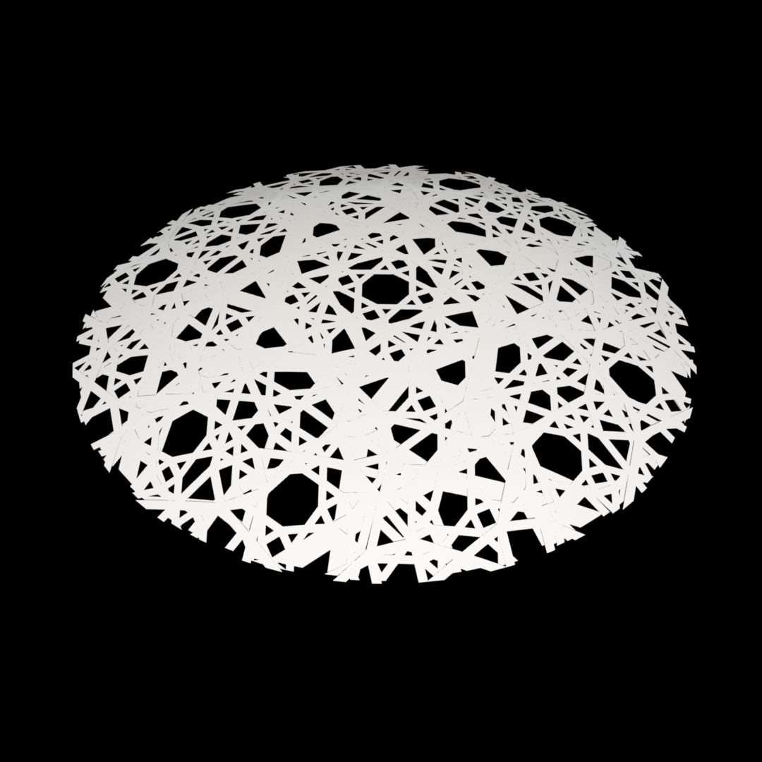
First we generate the flat pattern. note that the pattern in the image is affected by the sun.

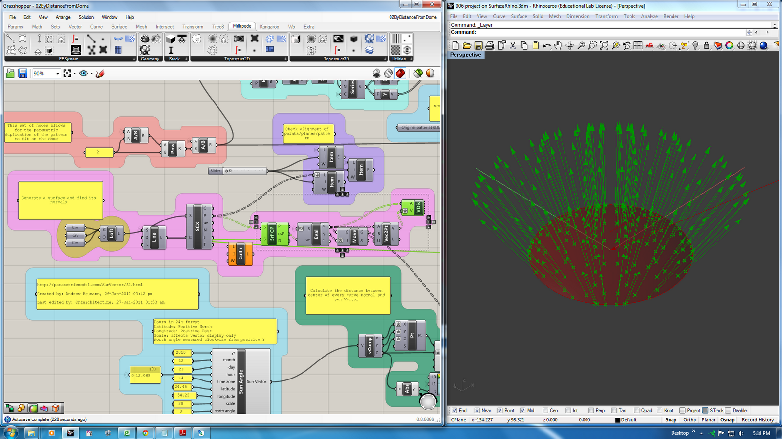
Then we create the sun and decide for which time of the year we are conducting the experiment. To do that, I have utilized a very nice Sun Vector node that can be found in this Sun Vector Link . The Sun Vector node allows for different parameters to be controlled which can simulate the location of the building and the different sun vectors throughout the year.

The series of nodes shown in the image are created to generate different points and planes for the pattern so that the number of panels on the dome can be parametrically controlled.

These nodes control the scale of the pattern on the dome which is also parametric.

Here we calculate the distance between each panel and the sun.

The distance is processed and then is passed to the offset parameters for the flat curves.

The flat curves are then projected on the dome.

Originally, I wanted to use Galapagos to analyze each step throughout the year in order to come up with the most efficient design for the patterns. However, because the projection process on the dome is processor and memory intensive, that idea was left for future exploration. Nevertheless, in order to prepare for that step, there are two options to generate the dome, one which uses poly Surface, the other uses a Mesh which is what is required by analysis/visualization plug-ins.

Project 2 method II : By distance from the Dome
Here we measure the distance between the conceptual sun and the dome. To do that, a series of points were generated from the flat pattern and are projected on the dome. It is important to generate these points from the pattern itself as each point will correspond to the curve that it was generated from, thus the distance to the point will affect the curve.

With this series of nodes we measure the distance between the sun and the points

The distance is then processed and passed to the curves which are offset based on the processed distance.

Finally we project the curves on the dome to generate the pattern.

Project 2 method II : By angle between the sun and the Dome
The same steps were followed as in the previous methods. However, now instead of the distance we measure the angle between the sun vector and the surface vectors. A VB node was used to reset the angle when the angle exceeds 90 degree.